


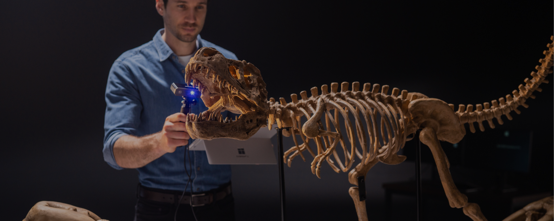


Accurately scanning deep crevices and hard-to-reach areas is a common 3D scanning challenge, so let's explore the best way to do it with a Revopoint 3D scanner.
Another Angle, Better Capture
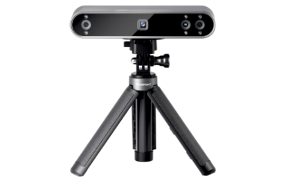
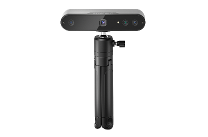
Let's begin by scanning a small object with the Revopoint MINI 2 3D Scanner. The scan starts in a horizontal orientation with two full rotations, capturing around 300 frames.

This quick scan gives a general capture of the object’s geometry. However, particular areas, especially deep recesses, appear incomplete or have significant gaps. Notably, some sections, such as undercuts or crevices (e.g., an "armpit" area), remain unscanned due to the scanner's angle limitations. Its depth cameras and projector cannot effectively see these areas from a horizontal perspective.


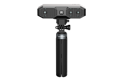
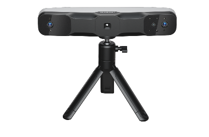
To address this limitation, an alternative approach involves rotating the scanner by 90 degrees for a vertical scan. For the best results, mount the scanner sideways to the tripod, as this offers consistent vertical scanning without awkwardly holding the scanner.
Scanning Tips
Before adjusting the scanner angle, first remove the tripod and then reattach the scanner sideways to it.

Changing the scanner's angle may flip your point cloud. You can fix this by adjusting the view to portrait in the preview window via the orientation button in the depth camera settings.


After adjusting the device, perform another quick scan with around 300 frames over two rotations and fuse the point cloud. Comparing the datasets shows that large gaps are significantly reduced, especially in narrow crevices, resulting in a more complete 3D model.


Some new blind spots may appear on elevated surfaces like shoulders, but previously problematic crevices are now better defined with fewer gaps or missing data. Merging horizontal and vertical scans will provide a more complete result.


Combining data from various perspectives compensates for each scan’s shortcomings, allowing a more comprehensive reconstruction of the object’s geometry. The merged scan shows greater detail than individual scans, demonstrating how strategic reorientation enhances the overall quality of the final model.
Understanding Why This Works
First, we need to look at the structured light scanner layout to understand why this works.
A central projector emits structured light patterns onto the objec. Blue light for the MINI 2 and infrared light for the POP 3 Plusand RANGE 2 models.
Depth cameras on either side of the projector capture a 3D shape of an object's surface from reflected light.
An additional RGB camera for capturing color information.

When scanning an object like a mug, the projector emits a fan-shaped light beam on its surface. The left and right depth cameras capture this pattern from different angles, enabling depth calculation and the capture of the 3D point cloud. However, areas obscured by features like handles may fall outside the cameras' view, creating blind spots in the scan data.


Let's apply this principle to scanning objects with deep crevices, like a vacuum filter with parallel ridges.
When scanned in a horizontal orientation:
- Each ridge casts shadows over adjacent sections.
- Blind spots form along every groove due to occlusion from neighboring ridges.
-The deepest parts of these crevices remain unscanned, hidden from both cameras.

By rotating the scanner vertically:
- The alignment between ridges changes relative to the camera’s perspective.
- More direct visibility into deeper sections is achieved.
-Combining multiple frames during continuous scanning reduces or eliminates blind spots.

(For a complete explanation, please refer to: https://forum.revopoint3d.com/t/steamkraft-tutorial-revopoint-mini-2-3d-scanner/23832)
Practical Tips & Considerations
Different types of objects require tailored approaches for optimal scan quality.
Complex Structures
Objects with gaps or overlapping parts (e.g., mechanical components, sculptures) benefit from multi-angle scans and data merging.
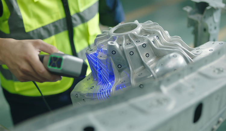
Highly Reflective or Transparent Materials
Glass and metal surfaces often cause reflection issues. Apply scanning spray to reduce glare and improve point cloud accuracy.
Marker-Based Tracking
Adding markers enhances stability and accuracy during scanning for objects with difficult-to-track surfaces.
Best Practices for Optimal Scans
Reorienting your scanner is effective, but actual scanning situations might need further strategies for the best results.
Use Multiple Orientations
Always perform scans from multiple angles (horizontal + vertical) to ensure comprehensive coverage.
Adjust the Object Position
Rotating or repositioning your object can further help expose hidden surfaces.
Use Marker-Based Tracking
Applying markers can improve alignment accuracy for highly detailed objects or those prone to tracking loss.
Merge Multiple Scans
Combining data from different orientations ensures complete geometry reconstruction.
Optimize Lighting & Exposure Settings
Proper exposure settings prevent overexposure or underexposure that could affect scan accuracy.
For more details, watch
Tutorial Video:
Scanning Principle Explained:
https://forum.revopoint3d.com/t/steamkraft-tutorial-revopoint-mini-2-3d-scanner/23832
Leave a comment
This site is protected by hCaptcha and the hCaptcha Privacy Policy and Terms of Service apply.